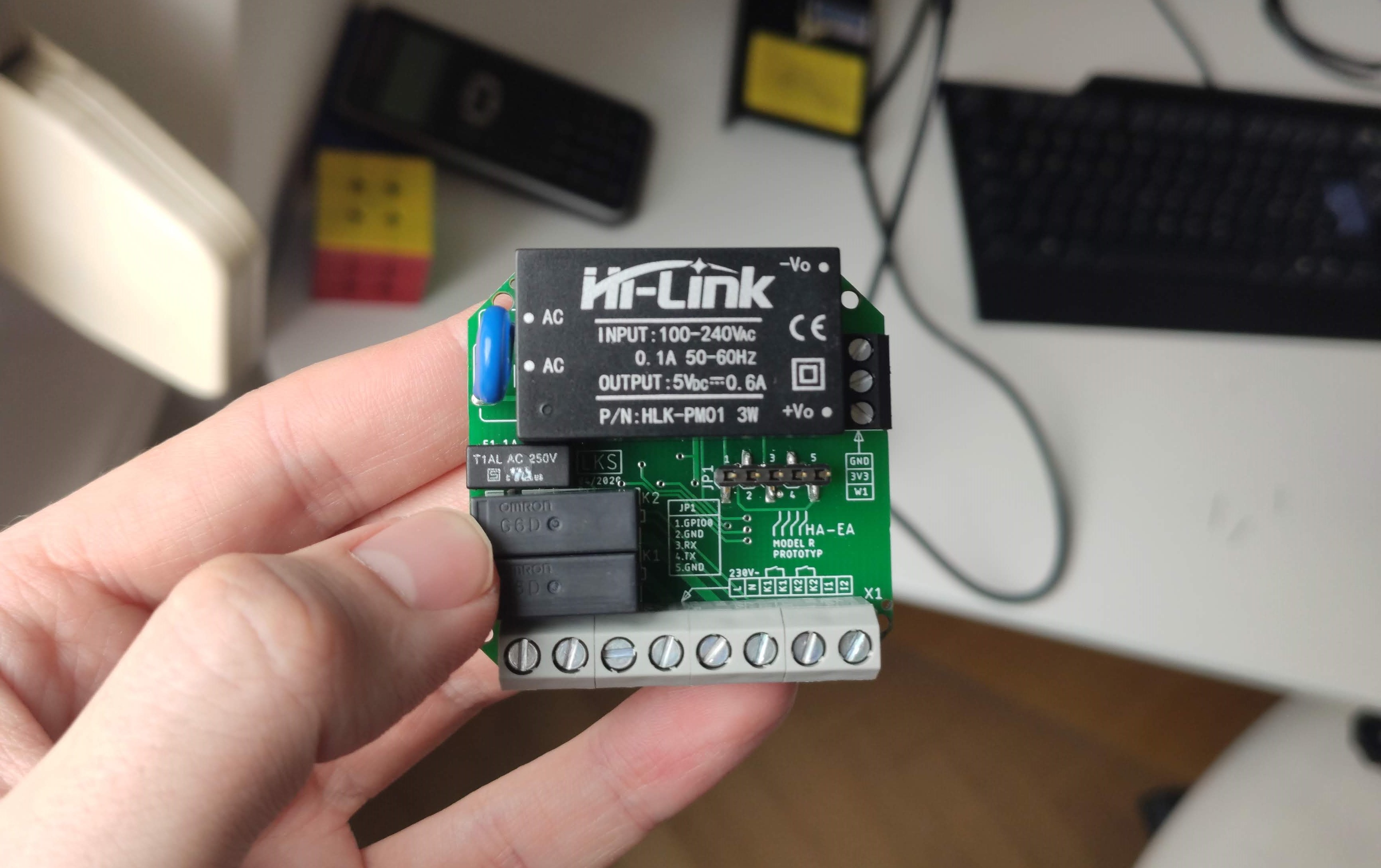
This document briefly describes all relevant features and shows the hardware specs of current HA-EA models. HA-EA is a range of devices that provide I/O to control devices and systems (e.g. heating and irrigation plants, lighting, domotics) and gather environmental data over an IP-based network.
Created: 16/07/2020
Last modified: 11/10/2021
Version: 4
Created by: Lukas D'Angelo
Model & feature overview
| Model | Ethernet interface | WiFi interface | Relay outputs | Digital inputs | Sensor BUS | Extension module |
|---|---|---|---|---|---|---|
| HA-EA-S | none | 802.11b/g/n | 8 | 0 | 1-Wire | HA-EA-S-EXT |
| HA-EA-ETH | 10/100BASE-T | 802.11b/g/n | 8 | 0 | none | HA-EA-S-EXT |
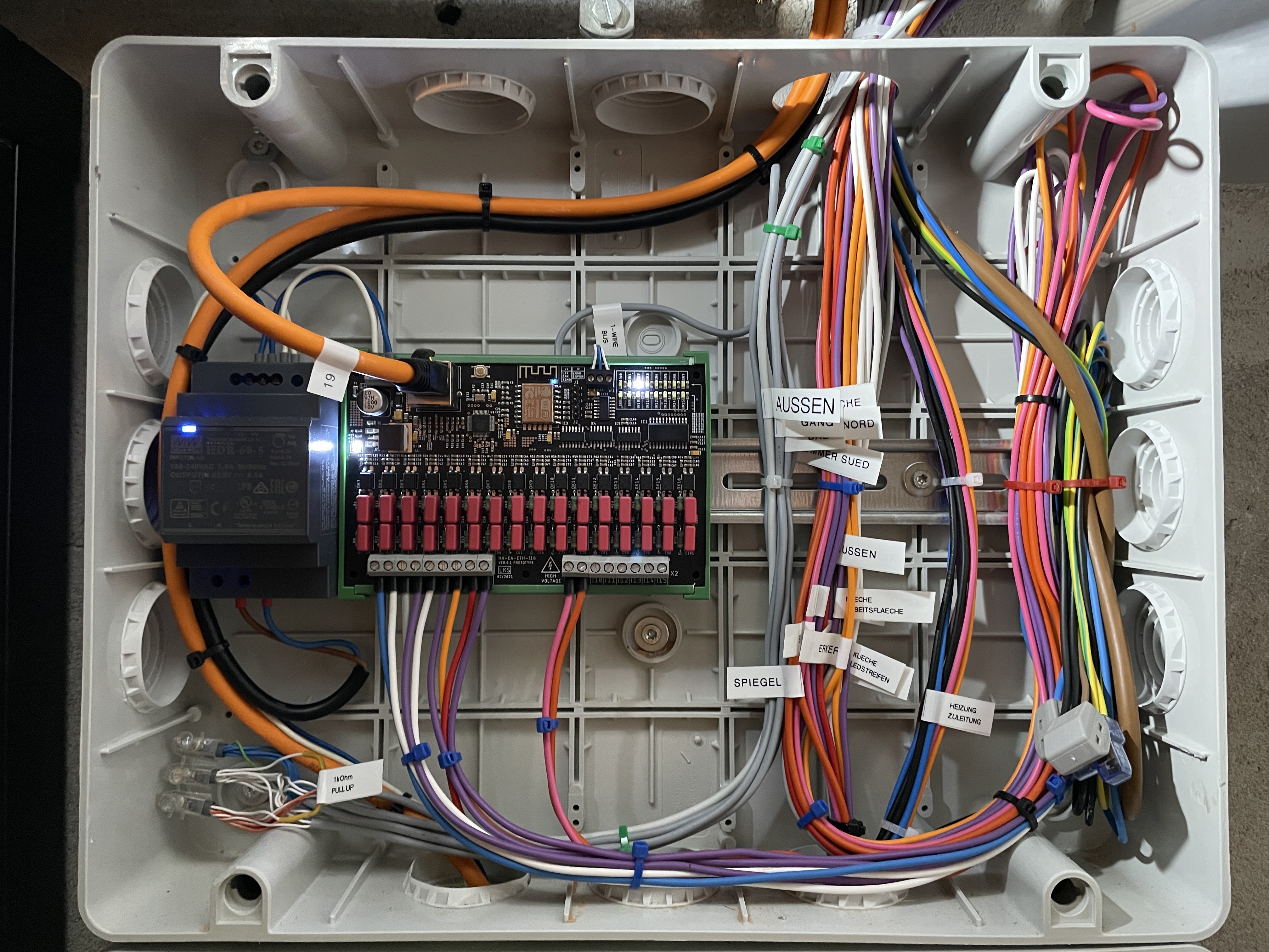
| HA-EA-I16 | 10/100BASE-T | 802.11b/g/n | 0 | 16 x 230V~ | 1-Wire | none |
| HA-EA-TL | none | 802.11b/g/n | 0 | 0 | 1-Wire | yes |
| HA-EA-R | none | 802.11b/g/n | 2 | 2 x 230V~ | 1-Wire | none |
Ethernet interface
A WIZnet W5500 IC provides ethernet connectivity. Auto negotiation is enabled by default, PHY-speed and DUPLEX-capability are gathered automatically. The TCP/IP stack is offloaded to the W5500 IC in order to reduce the load on the microcontroller when ethernet is used.
WiFi interface
The integrated WiFi-controller of the ESPRESSIF ESP8266 MCU is used to provide wireless connectivity.
| Wireless Interface | |
|---|---|
| Protocol | 802.11b/g/n |
| Frequency-Range | 2400MHz - 2483.5MHz |
| Security | WPA/WPA2 |
| Encryption | WEP/TKIP/AES |
| RX-Sensitivity 802.11b | -91dBm |
| RX-Sensitivity 802.11g | -75dBm |
| RX-Sensitivity 802.11n | -72dBm |
| TX-Power 802.11b | +20dBm |
| TX-Power 802.11g | +17dBm |
| TX-Power 802.11n | +14dBm |
Relay outputs
FUJITSU JV-5-KT relays (normal-open-contacts) are used to generate the digital output control signals. JV Series Datasheet
Digital inputs
The digital inputs are designed to sense the presence of 230V AC voltage. They can also be configured to sense DC or AC voltages (< 325V DC or < 230V AC) by populating the input stages of the devices with the appropriate resistors and capacitors for the desired voltage. The sampling period of the digital inputs is set to 1ms.
Note: All inputs share the same reference terminal (CM).
Sensor BUS
The sensor BUS is based on the Dallas Semiconductor 1-Wire protocol. Supported 1-Wire sensors:
- DS18B20
Extension module & stack operation
HA-EA-S and HA-EA-ETH (master) modules can be extended with HA-EA-EXT (slave). The extension module is a plug and play module, it does not need to be configuerd explicitly, only the master module has to be configured to enable stack operation. A master module can be extended with up to 5 extension modules, so the maximum number of relay outputs acheivable with one master module is 48. The master and slave modules are connected via a SPI BUS (5-PIN MOLEX PICOBLADE 1.25mm pitch connector).

Mechanical & electrical specification
HA-EA-S/HA-EA-EXT
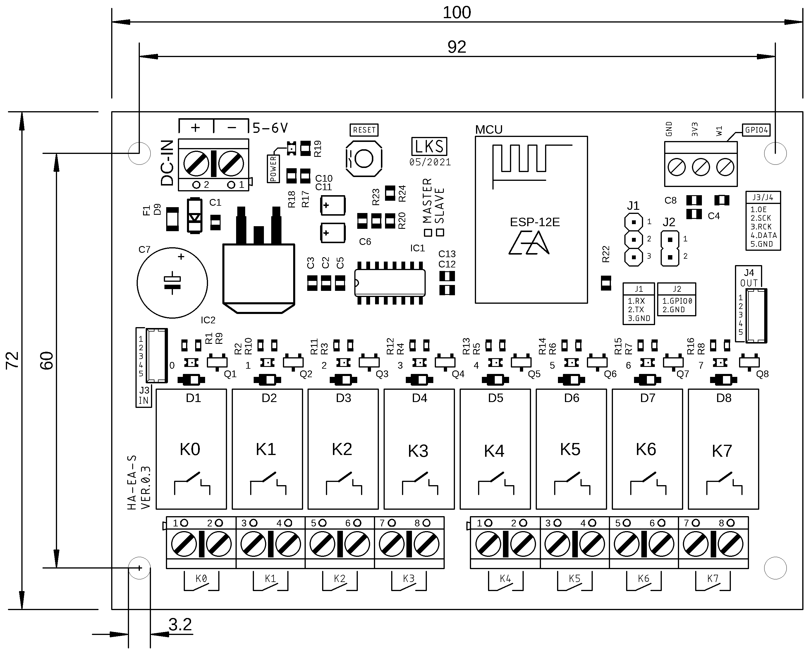
| Dimensions and weights | |
|---|---|
| PCB length | 100mm |
| PCB width | 72mm |
| PCB thickness | 1.6mm |
| Max. device height | 20mm |
| Weight | 90g |
| Mounting hole diameter | 3.2mm |
| DIN-Rail Mount Profile | UM72 |
| Electrical specifications | |
|---|---|
| Min. supply voltage DC-IN | 5V DC |
| Max. supply voltage DC-IN | 6V DC |
| Typ. current consumption | 0.2A |
| Max. current consumption | 0.5A |
| Built-in PTC fuse | 1A |
| Reverse polarity protection | YES |
| Serial interface level | 3.3V |
| Max. relay switching current (resistive) | 5A |
| Max. relay switching voltage | 250VAC/30VDC |
| Max. relay switching power | 1250VA/150W |
| Max. wire cross section relay terminals | 1.5mm² |
| Max. wire cross section DC-IN | 1.5mm² |
| Max. wire cross section W1 | 1mm² |
Note: Applies to HW-Version 0.3
HA-EA-ETH
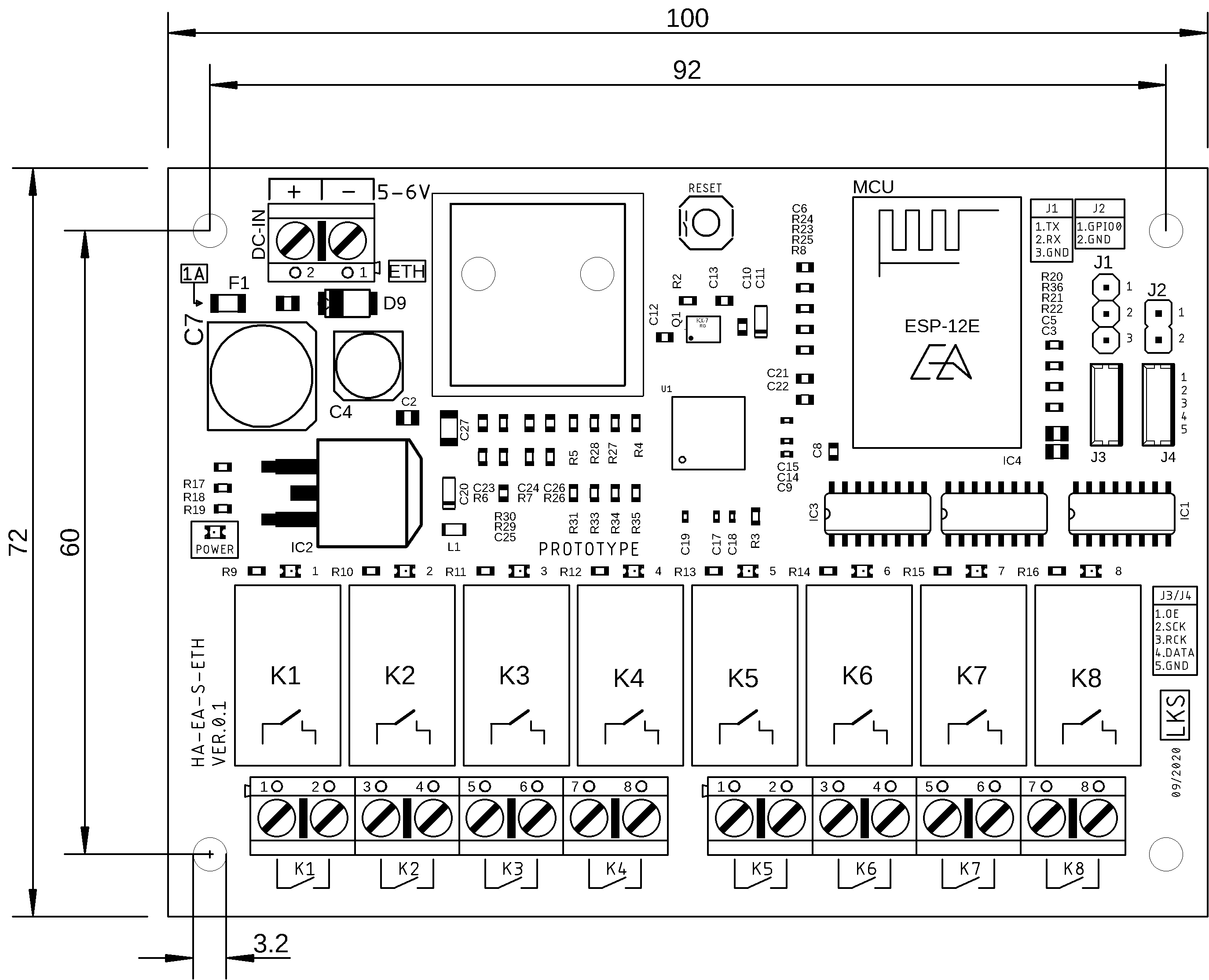
| Dimensions and weights | |
|---|---|
| PCB length | 100mm |
| PCB width | 72mm |
| PCB thickness | 1.6mm |
| Max. device height | 20mm |
| Weight | 95g |
| Mounting hole diameter | 3.2mm |
| DIN-Rail Mount Profile | UM72 |
| Electrical specifications | |
|---|---|
| Min. supply voltage DC-IN | 5V DC |
| Max. supply voltage DC-IN | 6V DC |
| Typ. current consumption | 0.3A |
| Max. current consumption | 0.6A |
| Built-in PTC fuse | 1A |
| Reverse polarity protection | YES |
| Serial interface level | 3.3V |
| Max. relay switching current (resistive) | 5A |
| Max. relay switching voltage | 250VAC/30VDC |
| Max. relay switching power | 1250VA/150W |
| Max. wire cross section relay terminals | 1.5mm² |
| Max. wire cross section DC-IN | 1.5mm² |
| Max. wire cross section W1 | 1mm² |
Note: Applies to HW-Version 0.2
HA-EA-I16
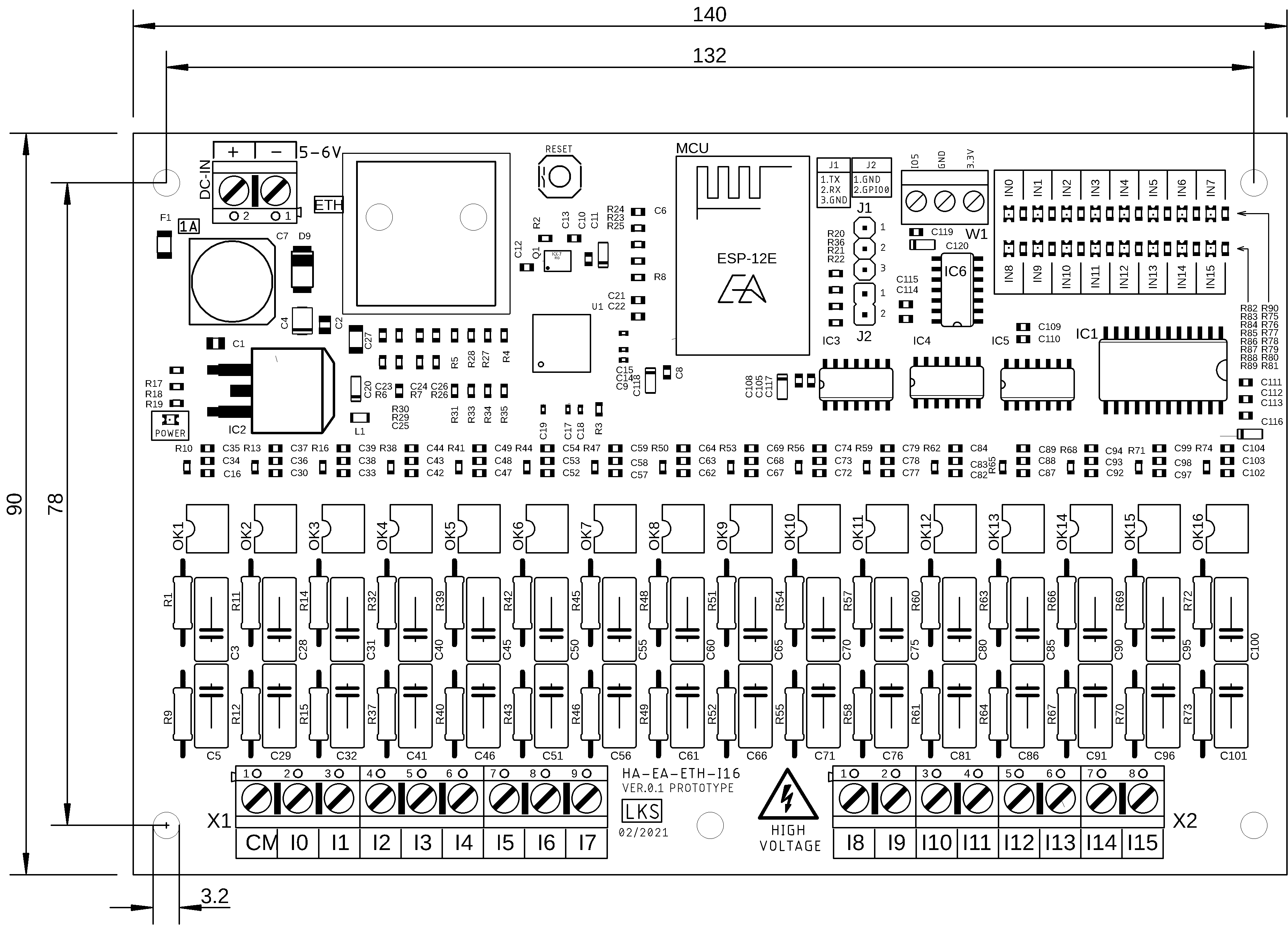
| Dimensions and weights | |
|---|---|
| PCB length | 140mm |
| PCB width | 90mm |
| PCB thickness | 1.6mm |
| Max. device height | 20mm |
| Weight | 95g |
| Mounting hole diameter | 3.2mm |
| DIN-Rail Mount Profile | UM90 |
| Electrical specifications | |
|---|---|
| Min. supply voltage DC-IN | 5V DC |
| Max. supply voltage DC-IN | 6V DC |
| Typ. current consumption | 0.3A |
| Max. current consumption | 0.3A |
| Built-in PTC fuse | 1A |
| Reverse polarity protection | YES |
| Serial interface level | 3.3V |
| Max. wire cross section input terminals | 1.5mm² |
| Max. wire cross section DC-IN | 1.5mm² |
| Max. wire cross section W1 | 1mm² |
Note: Applies to HW-Version 0.1
HA-EA-TL
| Dimensions and weights | |
|---|---|
| PCB length | 30mm |
| PCB width | 36mm |
| PCB thickness | 1.6mm |
| Max. device height | 20mm |
| Weight | –g |
| Mounting hole diameter | 2.5mm |
| DIN-Rail Mount Profile | custom |
Note: Hardware work in progress
HA-EA-R
| Dimensions and weights | |
|---|---|
| PCB length | 48mm |
| PCB width | 46mm |
| PCB thickness | 1.6mm |
| Max. device height | 20mm |
| Weight | 40g |
| Mounting hole diameter | 2.2mm |
| DIN-Rail Mount Profile | custom |
| Electrical specifications | |
|---|---|
| Min. supply voltage AC-IN | 100V AC |
| Max. supply voltage AC-IN | 240V AC |
| Typ. current consumption | 0.1A |
| Max. current consumption | 0.1A |
| Built-in fuse | 1A |
| Serial interface level | 3.3V |
| Max. relay switching current (resistive) | 5A |
| Max. relay switching voltage | 250VAC/30VDC |
| Max. relay switching power | 1250VA/150W |
| Max. wire cross section relay terminals | 1.5mm² |
| Max. wire cross section input terminals | 1.5mm² |
| Max. wire cross section AC-IN | 1.5mm² |
| Max. wire cross section W1 | 1mm² |
Note: Experimental device
Header & connector description
| Name | Description |
|---|---|
| DC-IN | Supply terminal |
| W1 | 1-Wire terminal |
| RESET | Button to trigger hard reset of the MCU |
| J1 | Header for serial connection (flashing and configuring) |
| J2 (pre-boot) | Jumper to trigger flash mode at boot |
| J2 (at boot) | Erases current configuration and loads default configuration |
| J3 | Chain IN header for stack operation |
| J4 | Chain OUT header for stack operation |
| Serial interface | |
|---|---|
| Header | J1 |
| Logic level | 3.3V |
| Baud rate | 9600 |
| Data bits | 8 |
| Parity | none |
| Flow control | none |
Schematics
Images
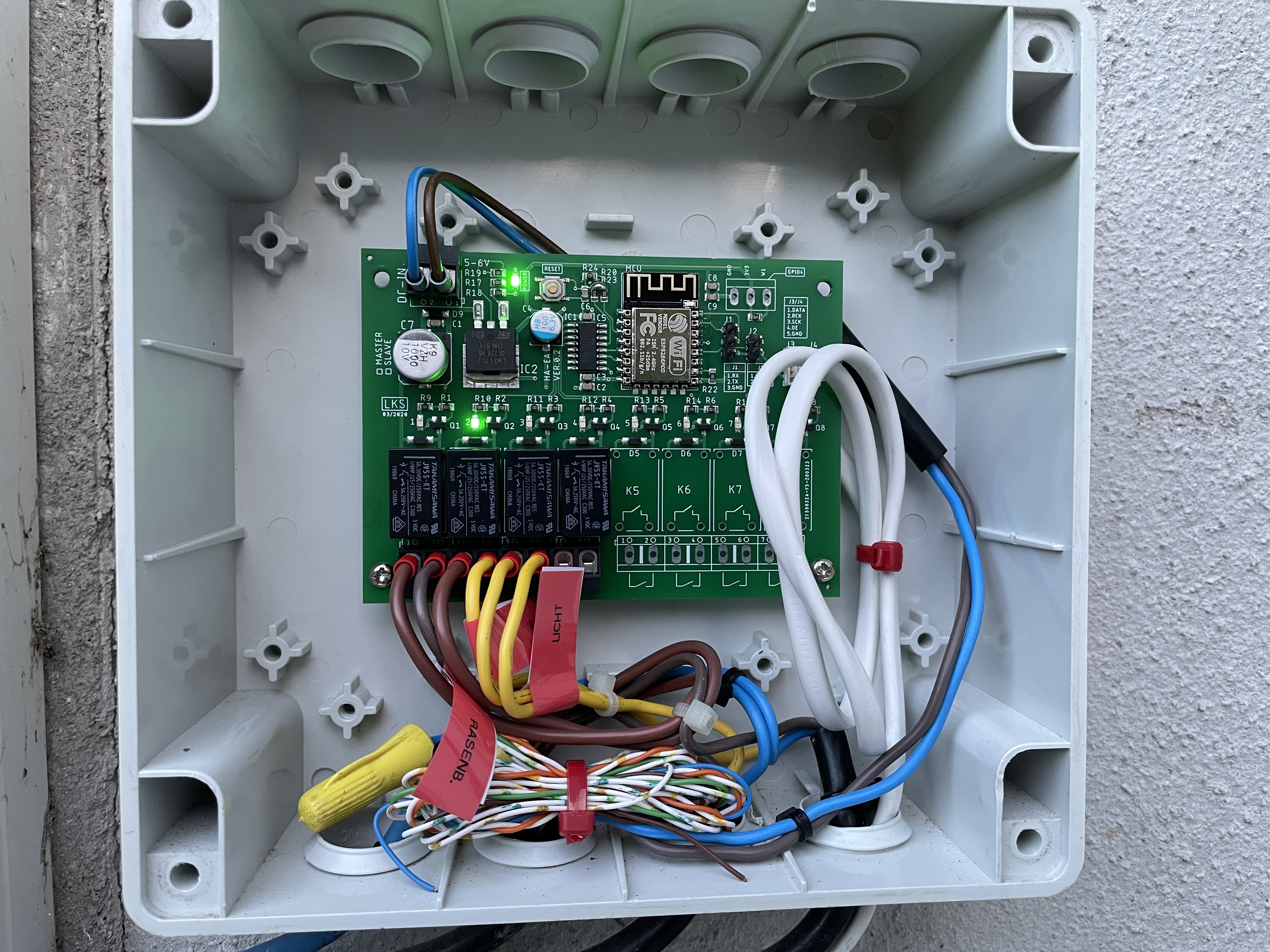
HA-EA-S
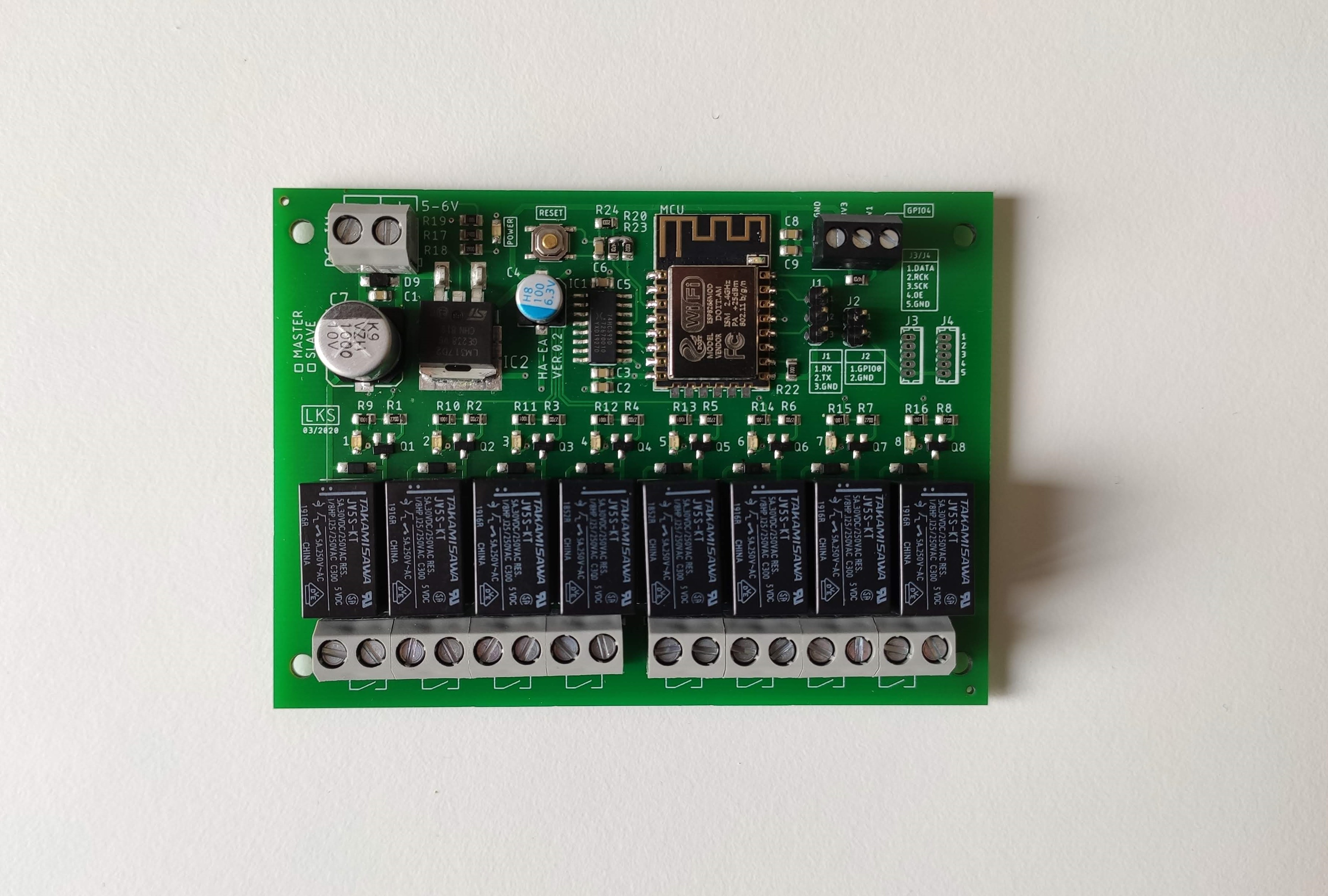
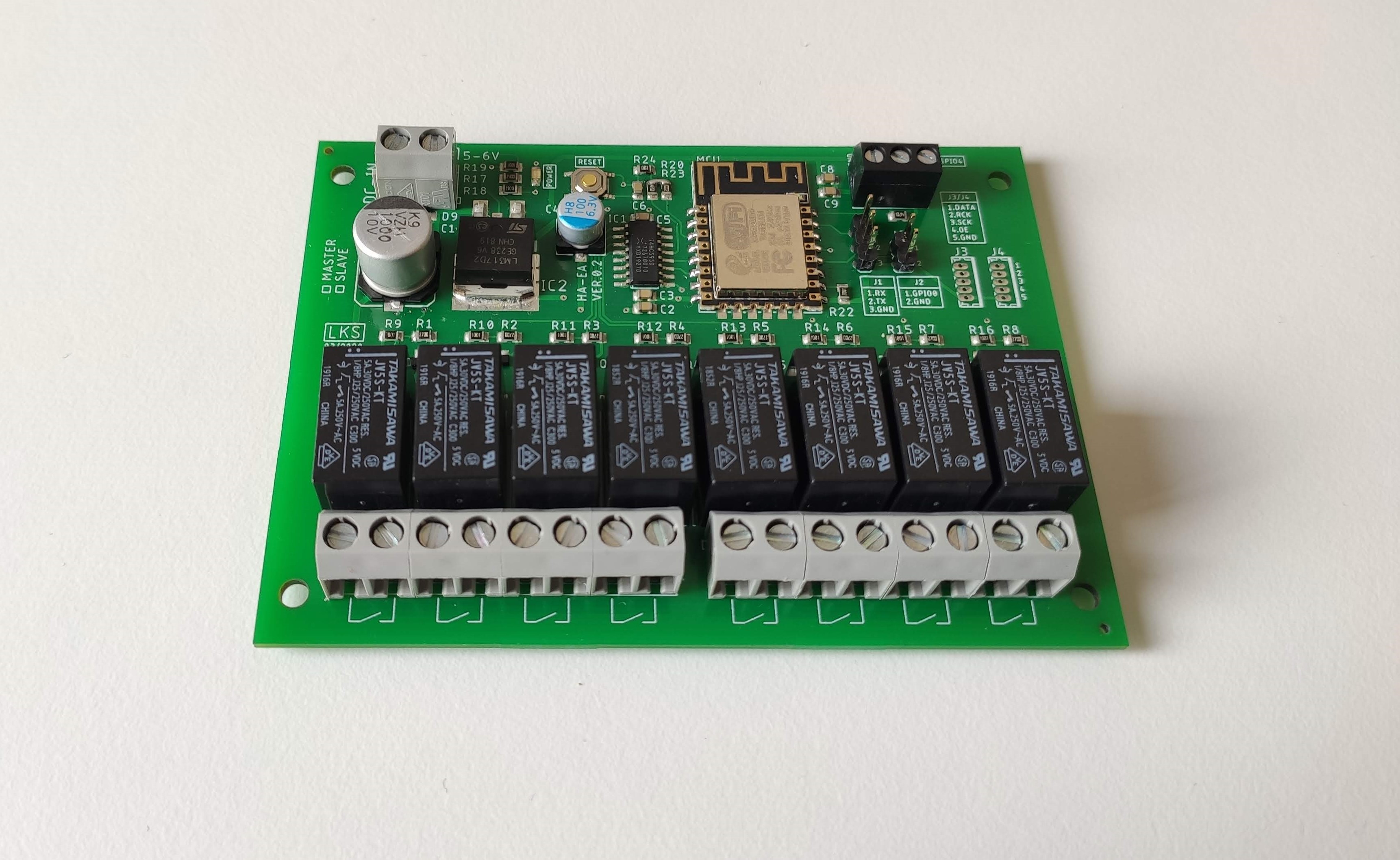
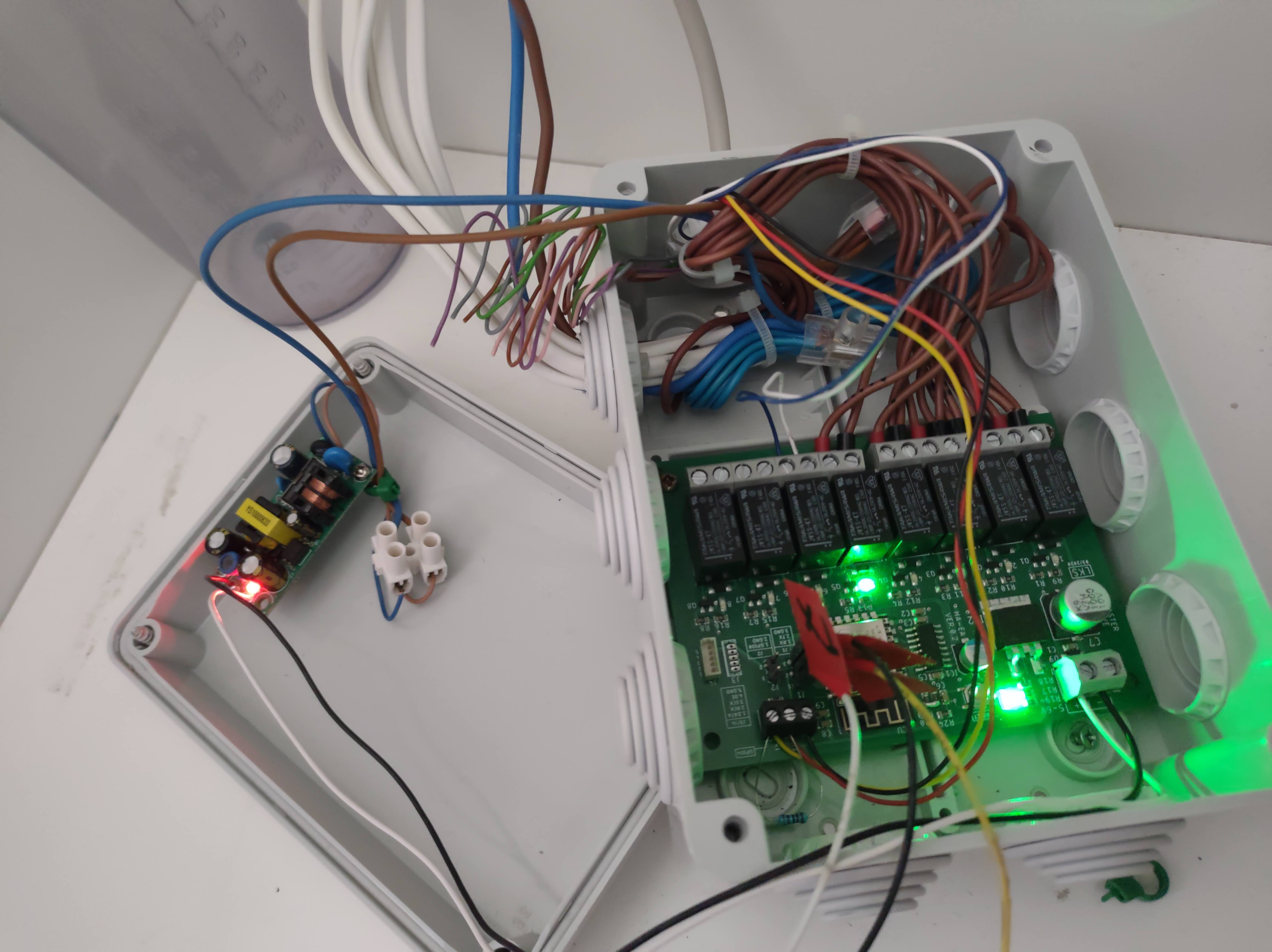
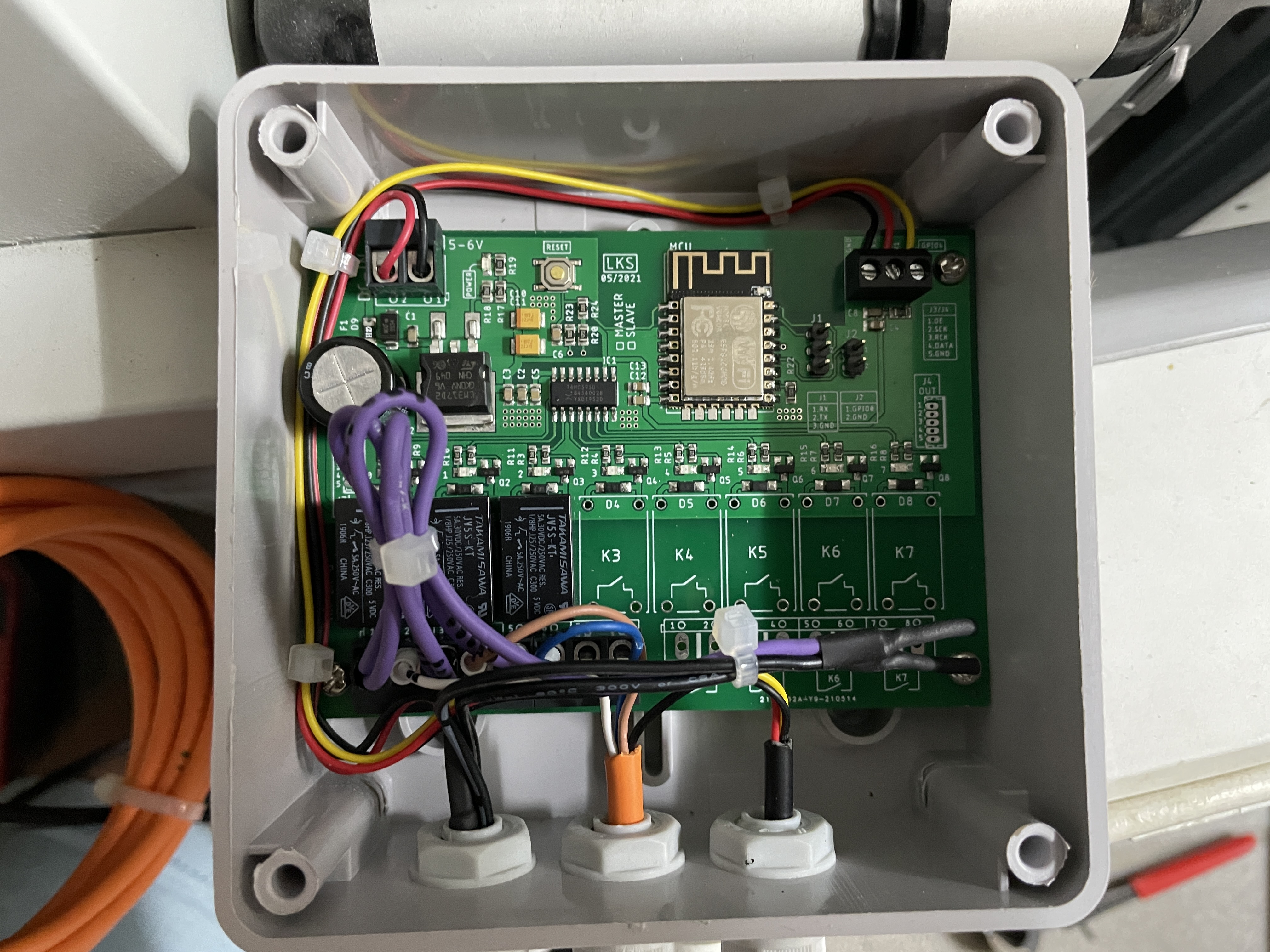
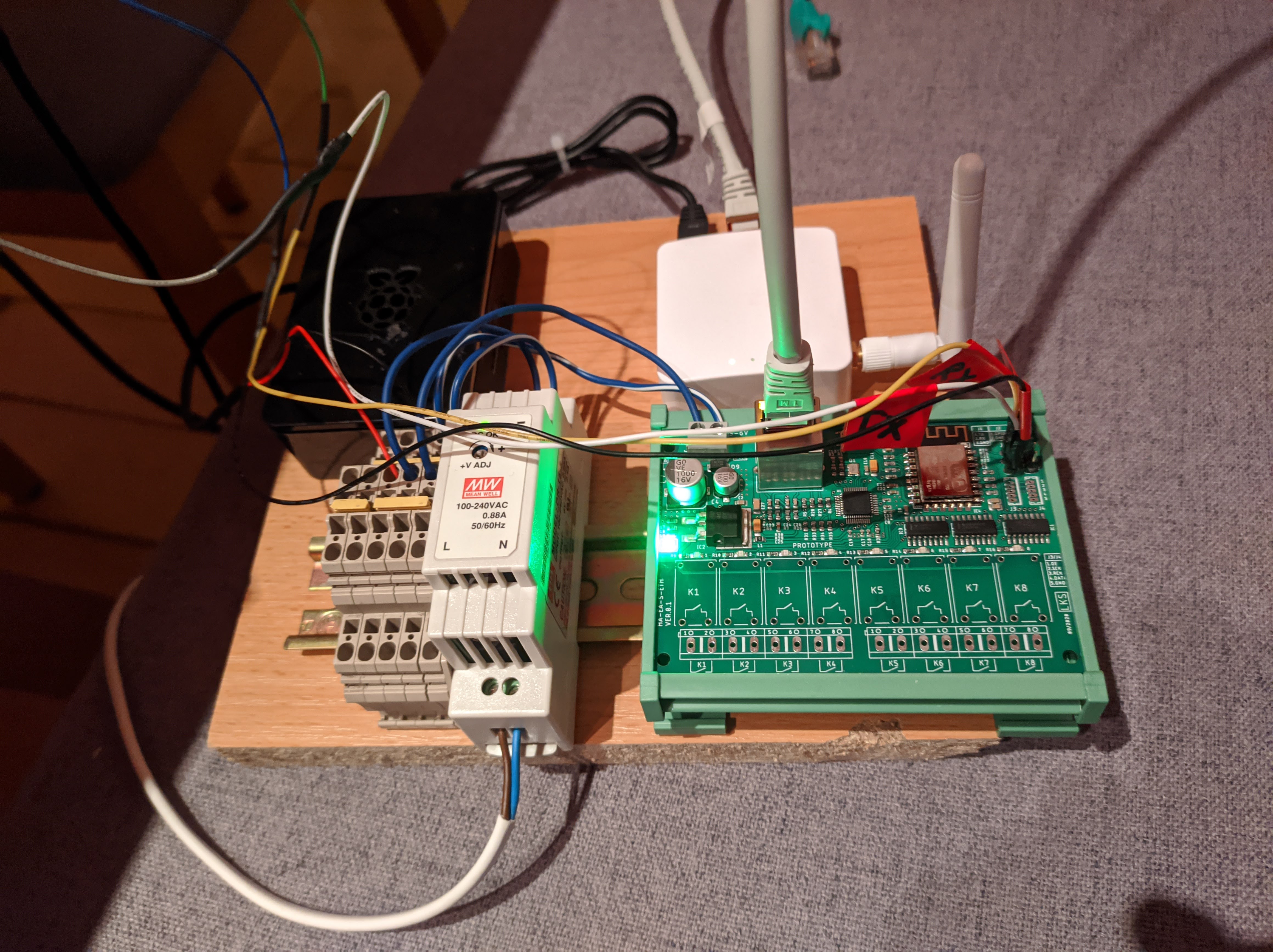
HA-EA-ETH
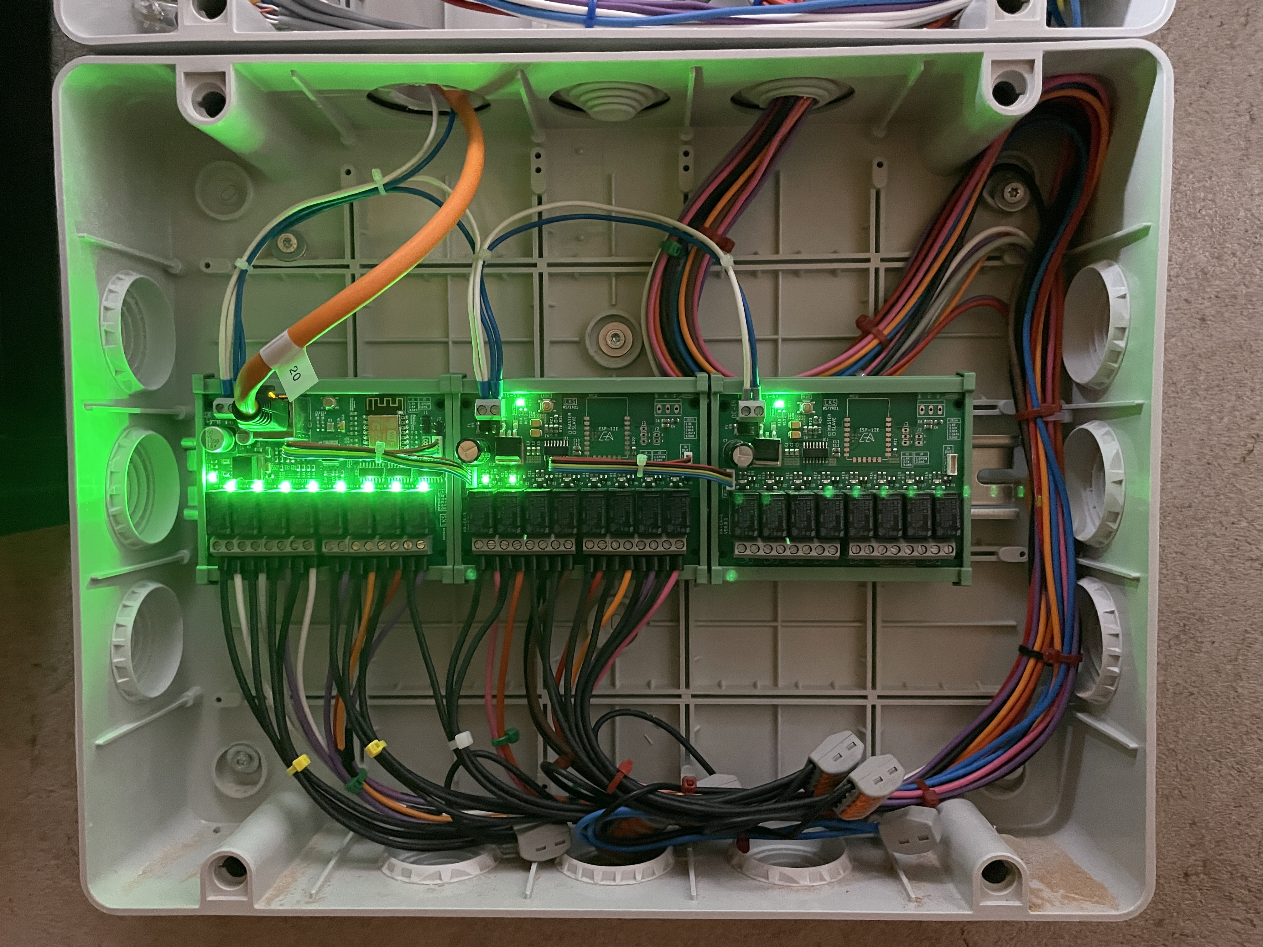
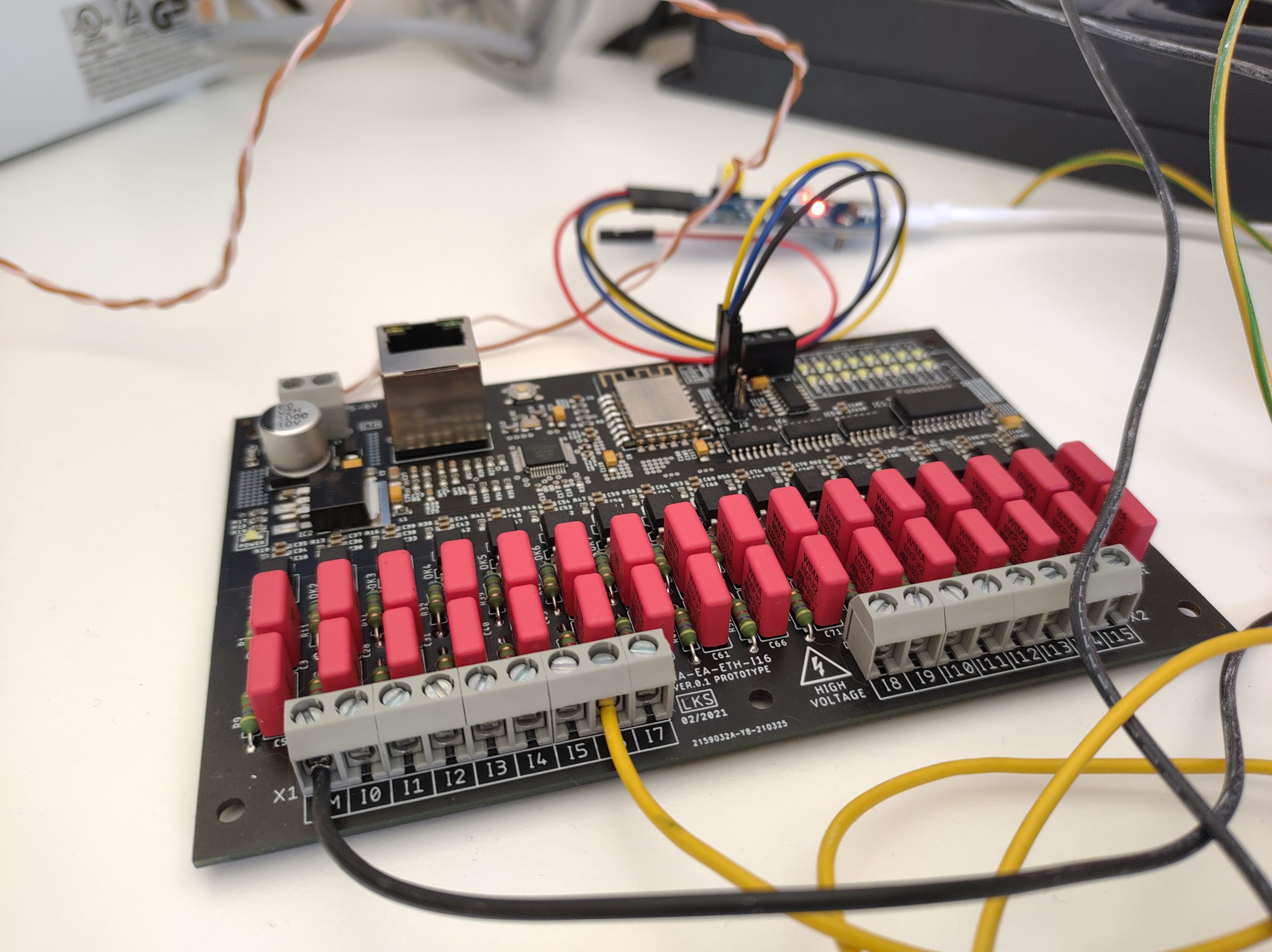
HA-EA-I16
HA-EA-R
